Knee Angle Data Logger
I mentioned in my team’s report that we considered using a quadrature encoder built into a servo motor for recording both speed and direction of the knee, but I decided against it because of its gearbox’s mechanical resistance to what would otherwise be ‘natural movement’. Months after the main project, I decided to design and construct a piece of wearable tech — an optionally-wireless knee angle data logger — to verify or disprove this assumption, for starters.


Wearing the knee angle data logger:

Wearing and testing the knee angle data logger by walking around and quickly flexing the knee at different angles:
It turns out that this likely has less of an effect than initially thought. In contrast, however, the lack of mechanical compliance even with at least some material flexibility, and the heavy rotational inertia of the device about the leg as it sways, are issues. In future work, the latter may be largely solved by making the sizable prototype of its data acquisition electronics more compact and/or offloading it elsewhere along and closer to the leg.
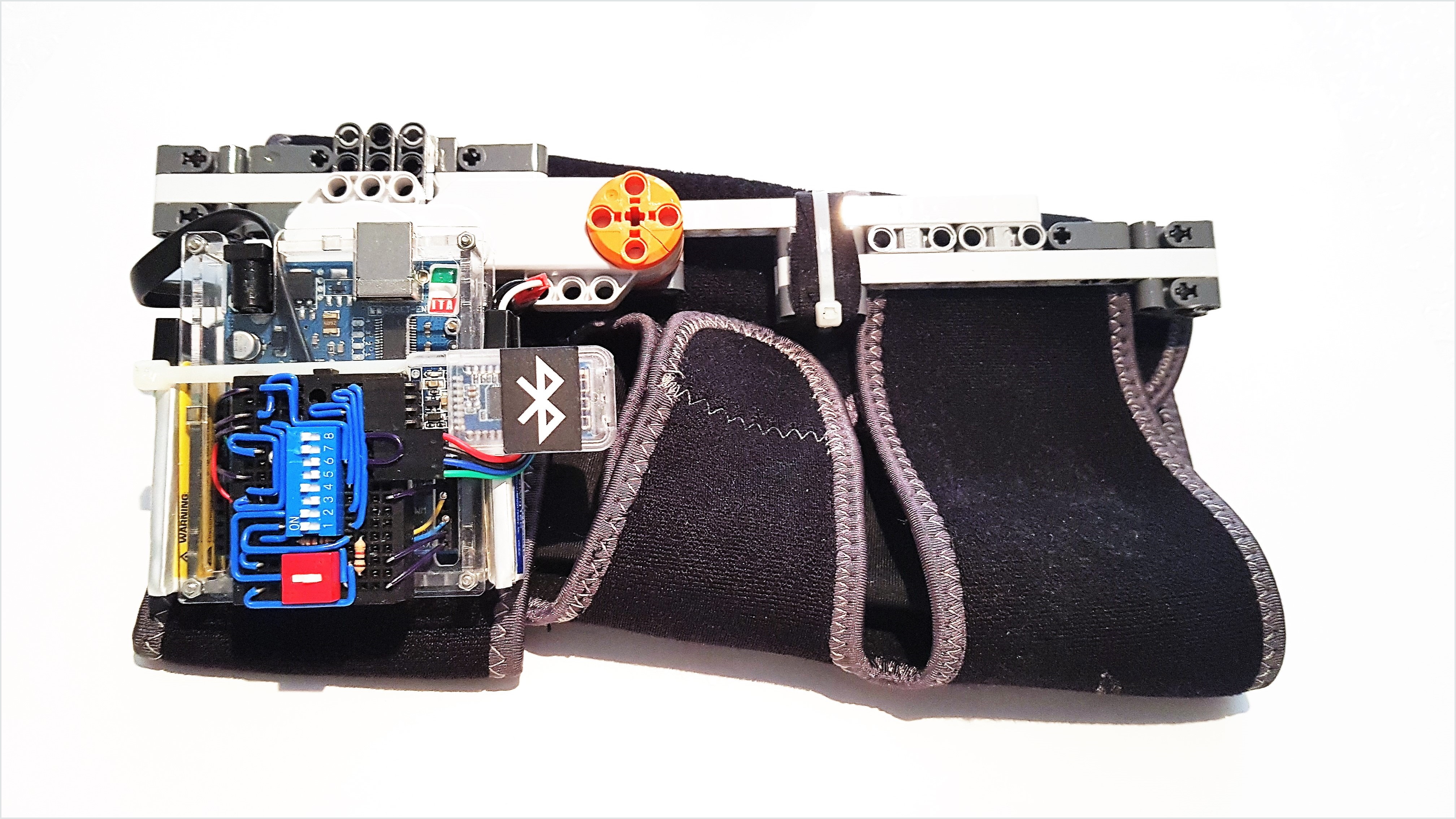
The device consists of the following.
An ergonomic fabric cuff/brace that velcro-straps around the leg — above, below, and at the knee.
An almost-servo motor (with a built-in quadrature encoder) — its housing and axle spanning the brace.
A microcontroller ‘unit’ (MCU) — in part to convert the encoder signals to an updated value of the knee angle.
A wireless transceiver — to transmit knee angle data to a phone.
Two rechargeable LiPo batteries — to power the MCU and the transceiver via the MCU.
A mini protoboard — to connect the previous three electrical parts/components.

❶ Generic representation of the servo motor (with a built-in but externally accessible quadrature encoder) — its housing and axle (❷) spanning the knee brace.
❸ The servo motor’s ‘six-position’ (6P) proprietary connection — or rather, a generic six-pin–header representation thereof.
❹ The pinout of ❸ and ❺ is as follows.
 |
Motor Negative |
 |
to MCU |
 |
Encoder Channel A |
 |
Motor Positive |
 |
to MCU |
 |
Encoder Channel B |
❺ The servo motor’s ‘six-conductor’ (6C) proprietary cable — a narrow ribbon cable.
❻ An Arduino MCU.
❼ MCU header pins — Digital I/O: (14 total)
RX<0receives via UART from a computer connected via USB OR from the Bluetooth module to the MCU, one communicating device at a time.TX>1transmits via UART from the MCU to a computer connected via USB AND to the Bluetooth module, at the same time.2receives the Encoder Channel B signal.4receives the Encoder Channel A signal.5is the enable input for transmitting knee angle data versus pausing the ‘transmission loop’.
❽ MCU header pins — Power:
Vinis the 7–12-V input to the MCU, thereby also to the servo motor’s encoder and the Bluetooth module.GNDis the voltage ground.5V0is the 5.0-V (operating voltage) supply from the MCU.RESETtemporarily ceases running any onboard program upon being shorted to ground.
❾ Power input port (2.1-mm center-positive connector) — not in use.
❿ USB (standard B) port — optional use with cable (⓫).
⓬ Mini protoboard (no bus strips, 17 rows of terminal strips, 170 tie points).
⓭ Set-length solid-core insulated protoboard wire (⓮ two are uninsulated).
⓯ (Brown) two resistors (1, 2 kΩ).
⓰ DPDT and ⓱ SPST dual in-line package (DIP) switches (see Appendix).
⓲ Two four-pin headers (actually laid flat against the protoboard) for the Bluetooth module and batteries.
⓳ Two pairs of battery leads.
⓴ Bluetooth module.
System Level Block Diagrams and Technical Details
Programming the Microcontroller
Programming the BLE Module
AT commands from any serial monitor, in the above case) to the BLE module (and vice-versa) through the microcontroller via USB.TX and RX pins.TX transmits via UART from the labeled device.RX receives via UART from a communicating device.GND pins).5V0 pin) and 3.3 V (microcontroller 3V3 pin), respectively.Logging Knee Angle Data (Default Operation Mode)
TX and RX pins.Appendix
Switch Position 1 |
Functionality |
Functionality |
|---|---|---|
Switch 6 · |
Shorts MCU |
Resets the MCU (temporarily) |
Switch 5 · |
Shorts 7.4 V to MCU |
Powers on the device |
Switch 4 · |
Shorts BLE module |
Powers on the BLE module thereafter |
Switch 3 · |
Breaks MCU |
Enables knee angle data transmission (default operation mode) |
Switch 2 · |
Shorts the MCU |
Enables wirelessly transmitting data — logging knee angle data |
Switch 1 · |
Shorts the MCU |
Enables wirelessly receiving data |
Switch 0 · |
Sets the MCU |
Enables logging knee angle data (default operation mode) |
Switch 0 · |
Sets the MCU |
Enables programming the BLE module |
- 1
Switch 0 is DPDT (double-pole, double-throw). Switches 1–6 are SPST (single-pole, single-throw). (Switches 7–8 are kept closed, 7 as a jumper.)